Advanced NDT
Long Range Ultrasonic Testing (LRUT)
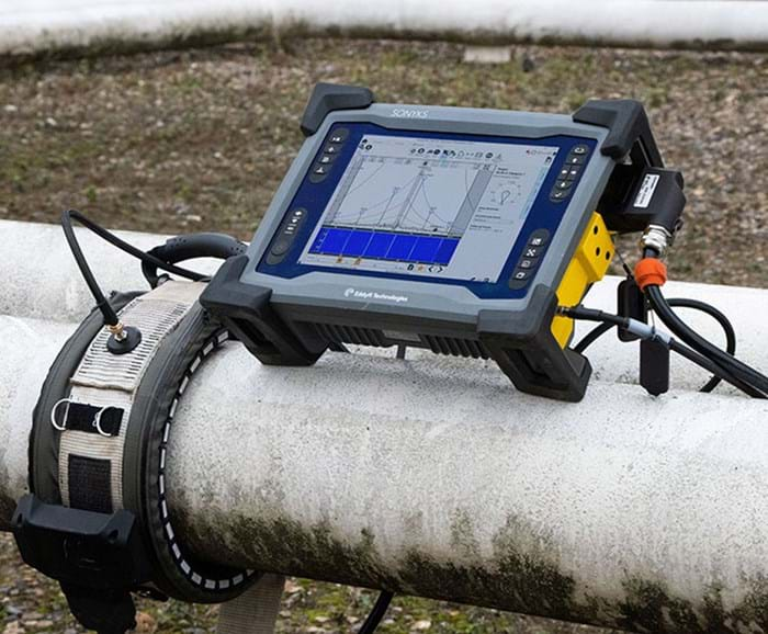
Long Range Ultrasonic Testing (LRUT) is an advanced nondestructive examination technique that was developed for testing large volumes
of material from a single test point. What differentiates this from more traditional methods of ultrasonic testing is that, with LRUT, a liquid couplant
between transducers and the surface is not required. For this reason LRUT is one of the fastest inspection tools for carrying out pipeline surveys for
corrosion and other damage mechanisms.
LRUT is an invaluable nondestructive testing technique that has applications throughout the oil and gas industry. It is widely used in the inspection of
pipes in areas such as road and river crossings, power plant tubing, risers, offshore topside pipework, jetty lines, and refinery pipework for the detection
of issues such as corrosion under insulation. It has also found widespread use in situations where pipes or tubes are not accessible to other detection methods
such as for pipes buried in soil, those encased in a sleeve, or those positioned at a high elevation.
Short Range Guided Wave Testing (SRGWT)
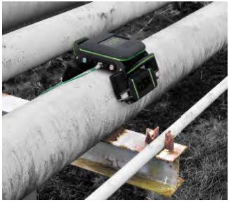
Short range guided wave testing (SRGWT) is an application of guided ultrasonic sound waves using special types of probes. When the guided waves hit
the discontinuities, the mode converted sound is reflected back and received by the transducer.
We have used this technique to detect corrosion on plates and pipes that are inaccessible due to support structures, braces, brackets, saddles, legs, under
insulations or other types of obstructions in the way of the region of interest. Our improvement to this technique is the use of QSR1 for corrosion under pipe support.
The QSR1® is GUL’s quantitative short range (QSR) device, incorporating the latest guided wave technology and hardware.
The system is designed to semi-automatically
scan predefined sections of straight pipelines for corrosion under pipe supports (CUPS). The QSR1® can provide a quantitative measure of the average wall, as well as the
remaining wall thickness down to half of the nominal wall thickness. This instrument is suitable for motorised guided wave scanning on predefined sections of straight pipelines,
with the added compatibility to operate with GUL’s cloud-based platform (CUPS)
Pulsed Eddy Current (PEC)
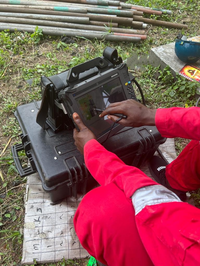
Pulsed Eddy Current (PEC): Is an advanced electromagnetic inspection technology used in detecting flaws and corrosion in ferrous materials typically hidden under layers of coating, fireproofing, or insulation, which we call lift-off. It is a technology that allows wall thickness measurement when the probe is not in direct contact with the surface we want to inspect. It should be noted that PEC is only a screening tool and provides relative measurement. It does not provide absolute measurement like ultrasonic testing
Internal Rotary Inspection System (IRIS)
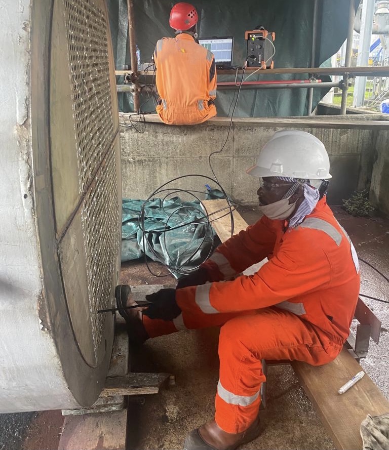
We use the internal rotary inspection system (IRIS) technique to inspect pipes and tubes, because IRIS is an ultrasonic technique, it requires a couplant - in this case, water.
Tubes under test must therefore first be flooded to use this technique. IRIS relies on a transducer to generate an ultrasonic pulse parallel to the axis of the tube under test. It also relies
on a rotating mirror that directs the ultrasonic wave into the tube wall. The mirror is driven by a small turbine powered by the pressure of water pumped into the tube. Part of the ultrasonic
wave is reflected by the inner-diameter (ID) wall, while the rest is reflected by the outer-diameter (OD) wall of the tube. Because the ultrasonic velocity of the tube’s material is known, it
is possible to assess the thickness of the wall by calculating the difference in times of flight between the two diameters. As the probe is pulled, the spinning motion of the mirror results in a helical scan path.
A critical aspect of IRIS is ensuring that the mirror is at the center of the tube. An off-center ultrasonic pulse yields a distorted scan image because of the different ID and OD wall sound paths.
That’s why our IRIS kits are equipped with centering devices helping operators keep the system centered. IRIS is commonly used in boilers, shell-and-tube heat exchangers, and fin-fan heat exchanger tubes.
Alternating Current Field Measurement (ACFM)
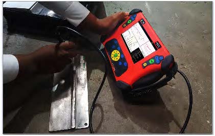
Alternating current field measurement (ACFM) is an electromagnetic technique used for the detection and sizing of surface breaking cracks in metallic components and welds. It combines the advantages
of the alternating current potential drop (ACPD) technique and Eddy Current Testing (ECT) in terms of defect sizing without calibration and ability to work without electrical contact respectively.
The ACFM probe introduces an electric current locally into the part and measures the associated electromagnetic fields close to the surface. The presence of a defect disturbs the associated fields and the information
is graphically presented to the system operator. The ends of a defect are easily identified to provide information on defect location and length. Through wall extent of the flaw plays an important role in determining
structural integrity and the same is calculated using mathematical computation thus allowing an immediate evaluation of the implication of the indication. ACFM inspection can be performed through paint and coatings,
hence it is considered to be a faster and economic technique than others e.g. magnetic particle inspection (MPI).
Phased Array Ultrasonic Testing (PAUT)
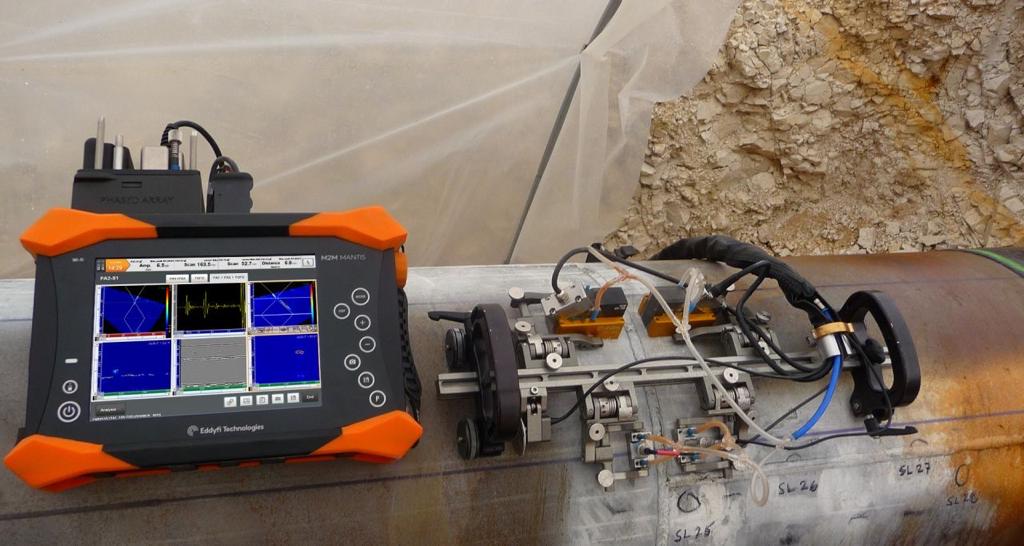
Phased Array Ultrasonic Testing (PAUT) is an advanced nondestructive examination technique that utilizes a set of ultrasonic testing (UT) probes made up of numerous small elements, each of which is pulsed
individually with computer-calculated timing. This technique can be used to inspect more complex geometries that are difficult and much slower to inspect with single probes. PAUT can be used to inspect almost any material
where traditional UT methods have been utilized, and is often used for weld inspections and crack detection.
Compared to other forms of UT, PAUT has several advantages. PAUT can be conducted more quickly than other forms of UT, often within a fraction of a second. It can easily be used for repeat scans because it has a high degree
of repeatability. By emitting beams of multiple different angles sequentially, PAUT is able to create detailed and accurate cross-sections of a part. It is also particularly useful in situations where there is less room for
mechanical scanning because it’s able to sweep the beam without moving the probe.
Magnetic Flux Leakage (MFL)

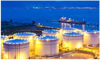
Magnetic flux leakage (MFL) is a magnetic method of non-destructive testing that is used to detect corrosion, pitting and wall loss in steel structures. Magnetic flux leakage (MFL) is commonly used for inspecting tank floors in the petrochemical industry. Corrosion of the tank floor can lead to the loss of product and cause damage to the environment. Therefore, it is vital that tank floor inspections are carried out in order to prevent the occurrence of such problems. MFL provides a cost-effective and high-speed inspection of tank floors. Our qualified MFL inspectors are backed by years of experience and have screened over 125 tank floors.
We use MFL equipment such as Floormap VS2i and Floormap 3D. The method uses permanent or electromagnets to magnetise the tank floor and the resulting magnetic field changes are recorded and analysed. If there is corrosion,
pitting or wall loss, the magnetic field ‘leaks’ and the ‘leakage’ is analysed to determine the location and severity of the defect of the tank floor – both near and far surface. A map of the corroded areas is provided with
the MFL method and this essential data can be stored for future reference and planning.
We are committed to ensuring our non-destructive testing inspections meet deadlines as we appreciate the importance of maintenance/outage schedules for industries such as petrochemical. By partnering with us, you have the Total Quality Assurance
of our in-depth expertise and the confidence that your maintenance/outage schedules will be met.
Digital Radiography Testing (DRT)
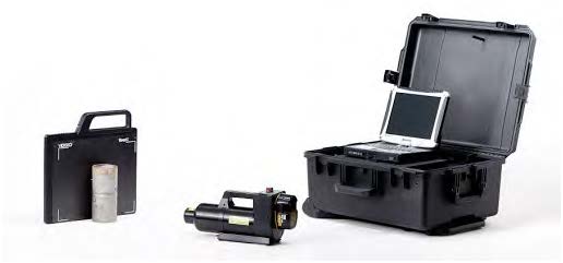
In contrast to film or Computed Radiography, Digital Radiography (DR) uses a X-ray digital image capturing device (Detector). This technology enables us to generate immediate and high quality X-ray images while keeping radiation levels to the minimum. Once generated the X-ray image is displayed on a tablet immediately, then using our User Friendly proprietary software the image can be processed, enhanced, shared and digitally stored and accessed on the spot.
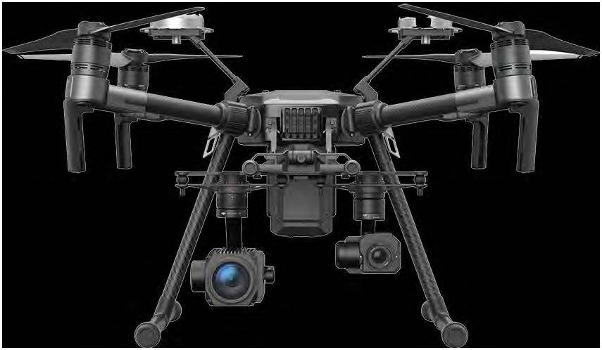
Drone (UAV) Inspection Solution
These days, drone inspections are being performed in almost every industry that requires visual inspections as part of its maintenance procedures. By using a drone to collect visual data on the condition of an asset, drone inspections help
inspectors avoid having to place themselves in dangerous situations.
Drone inspection offers easy access to hard accessible areas - be it bridges, pipelines, offshore flares and towers or other industrial constructions.
Benefits of drone inspection Using our drone inspection services for visual inspection, provide benefits such as:
- Inspection of areas difficult to access
- Preventive maintenance planning and optimised production
- Access to areas that pose health, safety and environmental risk to humans
- Quick on-site deployment of the drone inspection system Reduced downtime
- Authorised and qualified UAV-inspection personnel
