General NDT
Radiography
INDUSTRIAL RADIOGRAPHY – RT
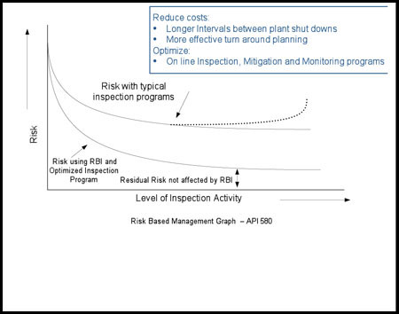
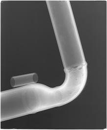
Radiography is a nondestructive test method that utilizes electromagnetic energy (radiation) from X-rays or gamma rays in order to detect
both surface and internal discontinuities. Radiography shadow shots can be used to inspect process piping, pressure vessels and valves, providing an easily
viewed and permanent record of the component that has been inspected. NDT has the ability to utilize either Computed or traditional film radiography techniques as per client specification.
NDT APPLIES RT
- For new fabrication weld inspection
- Code compliant inspection (ASME Section V for pressure vessels, ASME B31.1 and B31.3 for piping, API 1104 for pipelines, and others)
- For In-service weld and material inspection. Often, we determine the extent of internal and/or external corrosion/erosion in process piping, pressure vessels and valves
- Quick on-site deployment of the drone inspection system Reduced downtime
- For most metal and non-metal materials
ADVANTAGES
- Highly reproducible
- Images on films or digitized
- Data is stored for future comparison or audits
- Field ready
- Systems are portable and battery powered
- Light enough to easily take onto scaffolding
- Powerful setup tools to aid technicians in the field
LIMITATIONS
- Access to both sides of the test material is required
- Physical space is required
- Large areas adjacent to the component tested must be cleared from persons or items that may be affected by radiation.
- Environmental conditions may compromise film quality; low temperatures may slow down production
COMPUTED RADIOGRAPHY CR
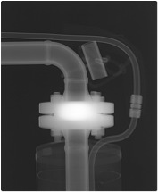
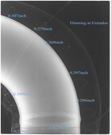
Computed radiography (CR) is used to assess internal or external corrosion/erosion losses in process piping, pressure vessels and valves. Based on it, one
can estimate remaining thickness and wall losses. The computerized images allow easy data sharing and result in significant improvements in radiographic inspection productivity
as well as faster identification of defects.
NDT APPLIES CR TO INSPECT
- Piping for internal corrosion, for corrosion under insulation (CUI) and for localized losses (such as those which develop in sulphuric acid service)
- Valves and their internals for internal or external corrosion/erosion
- Piping and valves for build-up of products and for blocks
- For losses in boiler tubes at temperatures of the order of 662 ⁰F
- Asbestos insulated equipment and assess losses around the circumference (not only those perpendicular to the radiation source)
ADVANTAGES
- The images can be readily shared, e-mailed and stored electronically by anyone needing reliability information for the equipment.
- The imaging plates practically eliminate re-shots by providing a greater range over which exposures can be useful.
- Reduction of exposure times from 50-70% when using IR 192
- Similar or better results are obtained when utilizing Se 75, Co60 and X-rays
- Images on film or digitized
- Data is stored for future comparison or audit
LIMITATIONS
- Radiation safety considerations are the same for CR as standard radiography
- An equipment reading station is required to scan the imaging plates
- Physical space and on-site electrical power are required to set up the equipment
- Requires access to both sides of the part
CR FUNDAMENTALS
Computed radiography (CR) uses phosphor-imaging plates instead of film to store radiographic inspection results. CR imaging plates are exposed as per standard
radiographic testing, but the images are laser scanned from the plates into a computer system. Using powerful software one can then analyze, manipulate, print and
store the images for future review. The remaining wall thickness can then be determined for ASME code weld interpretations and wall loss evaluations.
Computed radiography can be performed on the same materials and in the same situations as standard radiography. NDT uses CRxFlex, in conjunction with GE’s Rhythm
software, which allows the user to acquire, review, report and archive inspection data. The DICONDE-compliant Rhythm platform also permits image enhancement and data
sharing to provide significant improvements in productivity and faster identification of defect indications.
ULTRASONICS
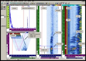
Ultrasonic Inspection is a non-destructive testing method capable of detecting both surface and sub-surface flaws in components and welds. UT can also be
used to measure the thickness of materials, a common method of evaluating metal losses due to corrosion or erosion.
NDT APPLIES UT
- To determine the extent of internal and/or external corrosion/erosion in process piping and pressure vessels
- For new fabrication weld inspection to verify code compliance
ADVANTAGES
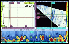
- Ultrasonics can be used to detect, locate and characterize flaws that other NDE methods cannot
- Some capabilities of determining the size, orientation and nature of internal flaws
- High penetrating power for detection of defects deep in the material
- High sensitivity allowing for location of extremely small flaws
- Only one surface needs to be accessible
- Systems are portable and battery powered
- Non-hazardous to operations or other nearby personnel, and has no effect on equipment or materials in the vicinity
LIMITATIONS
- Parts that are rough, irregular in shape, or very small or thin are more difficult to inspect
- Surfaces must be prepared by cleaning and removing scale, loose paint etc. prior to inspection
- Manual operation requires careful attention by experienced technicians
MAGNETIC PARTICLE – MT
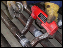
Magnetic particle inspection (MT) is a non-destructive testing method used to detect surface and slightly subsurface flaws in
ferromagnetic materials (such as carbon steel). It is used routinely to inspect welds, piping, pressure vessels and structural steel components.
NDT APPLIES MT TO INSPECT
- New fabrication welds for code compliance to ASME Section V for pressure vessels, ASME B31.1 & B31.3 for piping and API 1104 for pipelines
- Castings and forgings, valves and their components, machined parts, pressure vessels, cranes and structural steel welds for cracks, non-fusion, cold laps
- In-service welds
ADVANTAGES
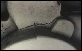
- Flaws are highly visible
- The equipment is portable and can be battery powered, light enough to take easily onto scaffolding
- The equipment is non-hazardous to operations or other nearby personnel
- The equipment as no effect on equipment or materials in the vicinity
- The equipment is very good sensitivity to fatigue cracking, tight fusion, HIC and SCC
LIMITATIONS
- Surface must be accessible and must be clean and free from oil, grease, scale, etc
- Cannot detect deep subsurface flaws
- Instrumentation and aircraft components require demagnetization after being inspected; residual magnetization may cause them to malfunction
- May require a power supply that is not intrinsically safe
MT FUNDAMENTALS
The area to be inspected is prepared and ferrous iron particles are applied to the part. The particles may be dry or in a wet suspension. The piece is then
magnetized by direct or indirect magnetization, whereas the presence of a surface or subsurface discontinuity in the material allows the magnetic flux to leak.
If an area of flux leakage is present the ferrous particles will be attracted to this area, resulting in an indication. Test results are interpreted in accordance
with the appropriate specifications, or customer requirements. A detailed report is issued clearly identifying the locations of any discontinuities.
LIQUID PENETRANT TESTING – PT
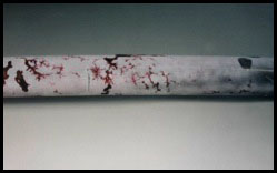
Liquid Penetrant Testing (PT) is used to detect casting, forging and welding surface defects such as hairline cracks, surface porosity, leaks in new products,
and fatigue cracks on in-service components. PT is a non-destructive examination method used to locate surface breaking discontinuities in non-porous materials (metals, plastics,
or ceramics). This method may be applied to ferrous and non-ferrous materials, although for ferrous components magnetic-particle inspection is often used instead for its subsurface detection capability.
NDT APPLIES PT TO INSPECT
- Welds and weld overlays, castings and forgings, valves and their components, machined parts, pressure vessels, clad vessel linings, and structural steel.
- New fabrication weld inspection
- In-service welds
- Ferrous and non-ferrous components
ADVANTAGES
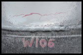
- High visibility of indications
- Low cost and fast results
- Can operate with battery power as well as supplied power when available
- Highly portable tools can be used in most locations
LIMITATIONS
- Can only detect surface flaws
- Conducting the test on rough surfaces, such as as-fabricated welds, will make it difficult to remove any excessive penetrant and could result in false indications
- Penetrants are limited by temperature and generally operate best in the range of 40 °F to 125 °F. Special procedure and penetrants can be used for temperatures outside this range but these must be qualified by a procedure test
- Test material must be relatively non-porous
POSITIVE MATERIAL IDENTIFICATION – PMI
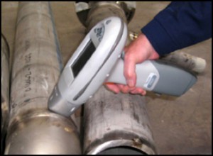
Positive Material Identification (PMI) is the analysis of a metallic alloy to establish composition by reading the percentage quantities
of its constituent elements. The object of this nondestructive testing method is to identify metal alloys in place using a portable X-Ray fluorescent analyzer
that determines the elemental composition of the material.
NDT APPLIES PMI
- To test ferrous and non-ferrous metallic materials, stainless steels, Monels, Inconels, Hastelloys, Aluminum alloys, nickel based alloys, exotic materials
- While verifying material compliance in power and petrochemical industries
- To inspect valves and valve components, pipe, fittings, machined parts, castings, forgings, bolts and stock items
- To inspect welds and weld overlays
- To verify compliance of new and in-service pressure vessels, plate material, and structural steel
ADVANTAGES
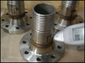
- Rapid and accurate analysis
- Highly portable digital technology, can be used on site
- Certifies components requiring NACE MR0175/ISO 15156
- Leaves no trace of testing on test sample
- Care must be taken to ensure that the surface of the test specimen is representative of the material as a whole
- The instrument must be able to maintain surface contact with the material
LIMITATIONS
- The depth of penetration of the x-ray for most elements is less than one thousandth of an inch in steel. Care must be taken to ensure that the surface of the material being analyzed is chemically representative of the whole
- Surface of the item must be accessible and subject to satisfactory cleaning and visual inspection
- Analyzers are limited to identifying only those alloys that are listed in the manufacturer’s library for the analyzer
- Material verification cannot be performed where the material temperature is in excess of approximately 200 °F, unless specialized equipment and techniques are used
- Identification of small amounts of a specific element in an item can be difficult
- Carbon, sulfur and phosphorous cannot be identified with x-ray fluorescence
PMI FUNDAMENTALS
Typical methods for PMI include X-ray fluorescence (XRF) and optical emission spectrometry (OES). IRISNDT carries out PMI using the latest portable analyzers. All analyzers have a margin of error that varies by element and activity of the radioactive source. The identification of small amounts of a specific element in an item can be difficult. Test results are summarized in an inspection report.
PORTABLE HARDNESS TESTING – HT
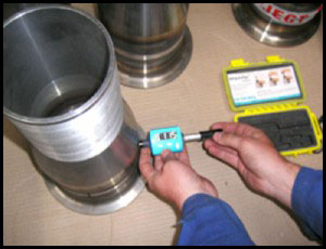
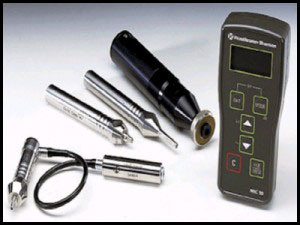
Portable Hardness Testing (HT) is a non-destructive testing method utilized to obtain the hardness value of a material. IRISNDT uses the latest GE Portable Hardness Testing Technology to provide clients the information they
require about the materials they are utilizing. NDT also employs full time metallurgists within our mechanical testing facility.
NDT APPLIES HT TO INSPECT
- Ferrous and non-ferrous metals and alloys, and select non-metallic materials
- Welds and weld overlays, weld heat affected zones (HAZ’s), castings and forgings, piping, stress relieved material, machined parts, pressure vessels, and structural steel
- Damaged materials as part of a failure analysis
- Welds and to verify material compliance to ASME Section IX and NACE MR0175/ISO 15156 requirements
ADVANTAGES
- Fast results and reporting to the client
- Field ready
- Highly portable tools can be used in most locations
LIMITATIONS
- Brinell hardness tests cannot be performed on thin material, in weld Heat-affected zones, and on surfaces where indentation are unacceptable such as finished machined surfaces
- MicroDur measurements require a surface polished to nearly a mirror finish
- The Equotip should only be used on parts with a thickness of ½” or greater
- When electric hardness testing equipment is in use, the temperature of the test material cannot exceed approximately 200 °F
FIELD SPECTROSCOPY – SPARK TESTING
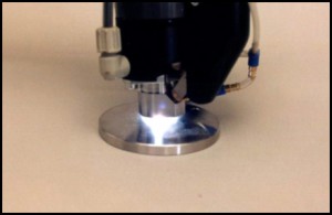
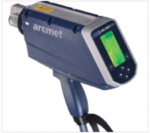
Spark testing involves the use of a field portable electronic instrument specifically designed to analyze metals and measure and quantify the chemical content. The instrument gives
elemental content of metallic and non-metallic compounds which make up the material under analysis and will give the percentage content of the elements present. NDT uses the Metorex ARC-MET 8000 for Field Spectroscopy analysis.
NDT APPLIES SPARK TESTING
- To determine whether the carbon, chromium and nickel dilutions in pressure vessel overlays are within the range required for optimized corrosion resistance
- To evaluate the carbon equivalent of an old part to be re-welded. Based on this, one can assess what special welding procedures may be required to make reliable repairs
- To insure that the correct grade of an alloy has been welded to a certain equipment circuit in petrochemical plants and refineries
- To sort materials. Based on the test, one determines whether different materials have been inadvertently mixed or whether batches of parts were made from the same raw materials
- For semi-quantitative analysis to provide information regarding the concentrations of specific elements in a metal sample
- For grade Identification to determine the concentrations of elements in an alloy and dentify whether or not the tested sample meets the user specified grade
ADVANTAGES
- Equipment is highly portable
- Results are obtained on-the spot with experienced technicians performing analysis
- Access to power source is required
LIMITATIONS
- Sample must have an overall thickness greater than 0.020 inch
- Test must be performed within specific temperature criteria to ensure both the accuracy of the analysis and the integrity of the equipment
- Testing is set up to analyze specific base models and will analyze for samples with an Iron, Nickel, or Copper base only. Analysis on other bases will render inaccurate readings
- Magnetic samples will cause disruption to the arc and should not be analyzed
- Clean surface representative of the material is required
FERRITE TESTING
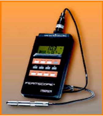
Ferrite content analysis is a non-destructive testing method which provides critical data for austenitic stainless steel and duplex materials. The delta ferrite percentage or number
allows a technical assessment of material corrosion susceptibility, mechanical properties, service suitability, and service reliability.
To perform properly ferrite testing, both a minimum material thickness and a minimum specimen size are required. Test results are interpreted in accordance with current specifications and/or
customer requirements. Reports issued are accompanied when necessary by drawings to identify locations tested.
NDT APPLIES FT TO INSPECT
- Austenitic stainless steel/Duplex stainless steels
- Normal construction steel with Austenitic chrome alloy steel welded cladding (Ex. Boilers, vessels, etc.)
- Weldments, Castings, Forgings, Weld Overlays, Wrought materials
- In-service and in-construction components
ADVANTAGES
- Rapid and accurate analysis
- Highly portable digital technology
- Variable calibration in both Ferrite Number (FN) and % Ferrite (FN) using AWS Standards
- Testing instrument meets all requirements of ANSI/AWS A4.2 and DIN EN ISO 8249
- Calibration is traceable to internationally approved IIW secondary calibration standards
LIMITATIONS
- Not recommended where the material is at temperatures greater than approximately 125 °F
- Surface preparation is very important for result accuracy
- Both a minimum material thickness and a minimum specimen size are required
- Shape of the specimen may have a negative effect on the results obtained. Correction calculations can be performed in some instances
